HALOX
HALogenOXide monitor
The HALOX instrument is designed for the measurement of chlorine monoxide (ClO) and bromine monoxide (BrO) in the lower to middle stratosphere (10-30km altitude range). In the stratosphere ClO and BrO do mainly originate from the decomposition of the manmade chloro fluoro carbons (CFCs), halons, and methyl bromide and are the main contributors to anthropogenic stratospheric ozone depletion. Their measurement quantifies the ozone depletion potential within a given air mass.
HALOX Setup
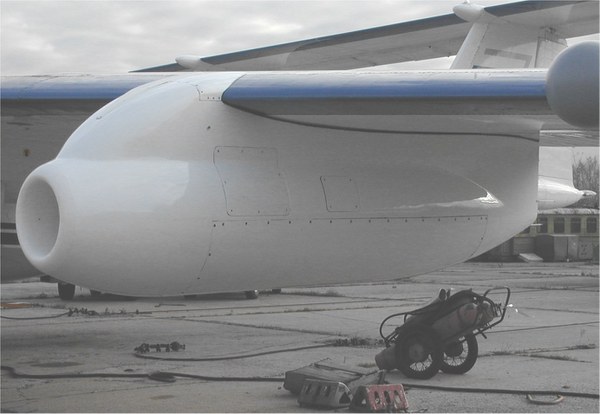
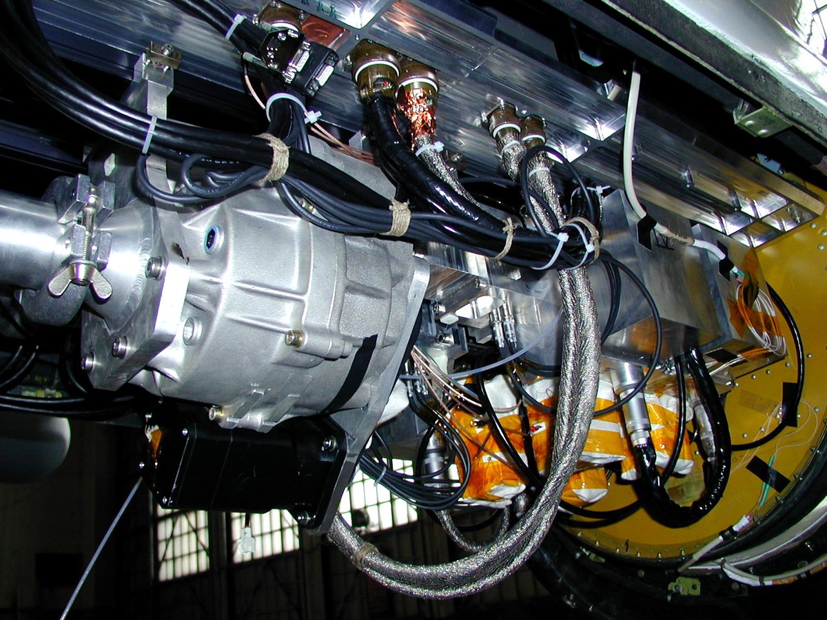
HALOX is placed in the wingpod under the left wing of the M-55 Geophysica. The instrument weighs about 130 kg and the overall dimensions are about 100 x 50 x 50 cm. It consists of two parralel measurement ducts suspended under the instrument base plate and the gas supply unit and electronics unit mounted on top of the plate.
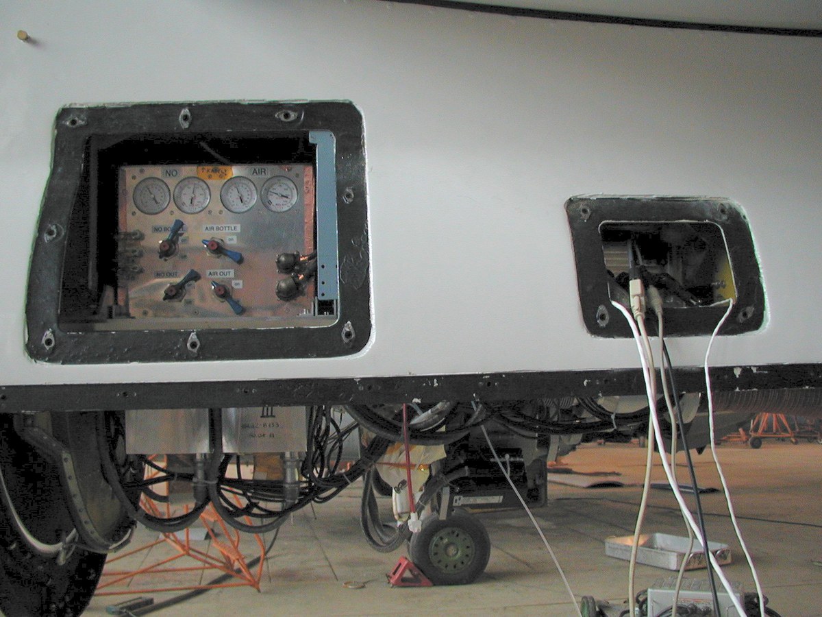
The electronics box consists of the instrument power supply units, the instrument control and data aquisition computer (486SX, 33MHz), control and interface electronics, and signal distribution panel. The gas supply unit carries two 1 l bottles for synthetic air, one 500 ml bottle for nitric oxide (NO), and several mechanical and electrical valves, gauges, and gas flow controllers.
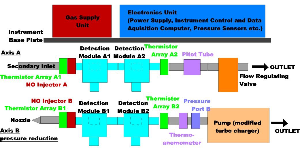
The two measurement ducts are operated in parallel: one operates at ambient pressure and one operates at reduced pressure in order to facilitate a more sensitive measurement of BrO where the RF lines are strongly absorbed by oxygen, and to enable a better time resolotion of around 10s.
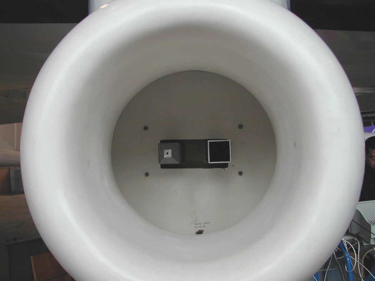
Both ducts consist of an air inlet, two thermistor arrays for temperature measurement within the air flow, the NO injector, two chlorine or bromine detection modules, and pressure sensor. The ambient pressure duct (A) has a flow regulating (butterfly) valve at it's end while the reduced pressure duct (B) has a nozzle at it's air inlet and a mechanical pump at it's end. The exhaust air of both ducts is combined and guided away from the instrument through an exhaust pipe.
Measurement Technique
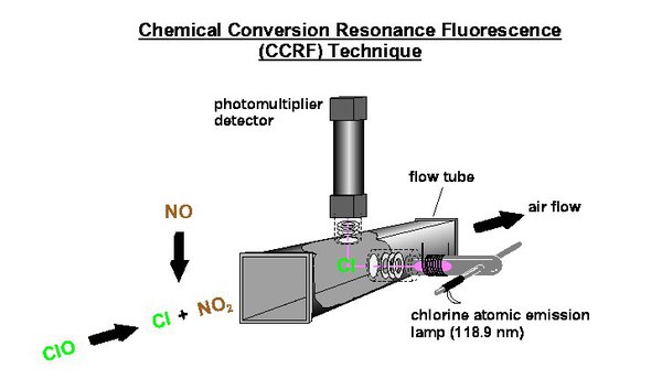
The instrument employs the chemical conversion resonance fluorescence (CCRF) technique to measure chlorine monoxide (ClO) (Brune et al. 1989a) and bromine monoxide (BrO) (Brune et al. 1989b) in-situ: Nitric oxide (NO) is added to a fast flow of ambient air through the instrument measurement duct. The reaction of the halogen oxides with NO forms halogen atoms on a millisecond time scale (ClO + NO --> Cl + NO2). The atoms are subsequently detected using rectangular arrangements of an appropriate atomic emission lamp and a photomultiplier detector which are located downstream. From the lamp emissions the Cl line at 118.9nm or the Br line at 131.7nm, respectively, are isolated using appropriate oxygen gas filters flushed with synthetic air. The NO addition is periodically switched on and off for 10s intervals in order to determine separately the background consisting of Rayleigh and chamber scatter and the RF signal due to the appropriate halogen atoms. With the proper calibration the halogen atom concentration in the detection volume can be inferred. The efficiency of conversion from the halogen oxides in the ambient air to the atoms is calculated using a kinetic model for the conversion reaction and the most important back reactions (e.g. Cl + O3 --> ClO + O2) employing the currently accepted reaction rates (DeMore et al. 1997). By periodically varying the NO flow as well as the air flow speed through the measurement duct the validity of the calculated conversion efficiency can be checked.
Calibrations
To guarantee the quality of the data laboratory calibrations based on Cl atomic absorption for the chlorine and bromine atom measurements before and after a field campaign will be followed. Chlorine and bromine atom calibration factors are determined by simultaneously observing the RF signal and the appropriate atom absorption signal which gives the atom concentration employing the absorption cross section as determined by Schwab and Anderson (1987). Bromine calibrations are linked to the chlorine calibration by titrating a quantified Cl atom concentration with an excess of bromine. Additional laboratory calibrations employing quantified amounts of the halogen oxides will be conducted in the frame of the ENVISAT validation measurements. Finally the atom calibration factors determined in the laboratory are related to the background scatter yielding a pressure dependent formula that is used to determine an in-flight calibration factor from the background observed during flight (Toohey et al. 1993, Brune et al. 1989a).
Instrument Specifications
The CCRF technique allows for the detection of ClO in the pressure range 10-200hPa and of BrO in the range 10-100hPa. The procedure detailed above provides an accuracy of 20% or 5pptv (whatever is higher) for ClO and 35% or 3pptv for BrO. The minimum time resolution of the measurements is given by the NO addition cycles and is around 20s or 10s for the double duct operation.
HALOX Upgrade to measure (ClO)2
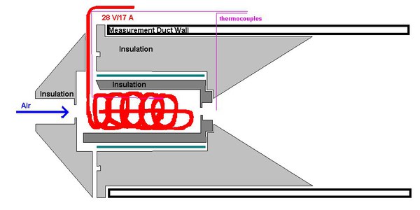
The latest addition to the HALOX instrument is a heated inlet nozzle (placed in front of the pressure reduced measurement duct), that allows for the in-situ measurement of the ClO dimer, (ClO)2, by thermally dissociating them to produce ClO which is detected using the CCRF technique employed by HALOX.
Campaigns
Moscow, Russia | 15.-30. Oct. 2001 | Integration and Test |
|---|---|---|
Forli, Italy | 8.-24. Jul. 2002 | Test for ENVISAT Validation |
Forli, Italy | 2. - 28. Oct. 2002 | ENVISAT Validation |
Kiruna, Sweden | Jan/Feb 2003 | EUPLEX |
Kiruna, Sweden | Feb/Mar 2003 | ENVISAT Validation |
Aracatuba, Brasil | Jan/Feb 2005 | TROCCINOX |
Oberpfaffenhofen, Germany | March 2005 | Arctic Vortex flight |
Darwin, Australia | Nov/Dec 2005 | SCOUT-O3 |
Oagadougou, Burkina Faso | August 2006 | AMMA |
Oberpfaffenhofen, Germany | November 2009 | PremierEx Test Campaign |
Kiruna, Sweden | Jan - Mar 2010 | RECONCILE |
Kiruna, Sweden | March 2010 | PremierEx |
Kiruna, Sweden | December 2011 | ESSenCe 11 |
Contact
Dr. Fred Stroh
Tel: +49 (0)2461 614703
Dr. Marc von Hobe
Tel: +49 (0)2461 614620
References
Brune, W.H., J.G. Anderson, and K.R. Chan, In Situ Observations of ClO in the Antarctic: ER-2 Aircraft Results From 54°S to 72°S Latitude, J. Geophys. Res., 94, 16,649-16,663, 1989a.
Brune, W.H., J.G. Anderson, and K.R. Chan, In Situ Observations of BrO Over Antarctica: ER-2 Aircraft Results From 54°S to 72°S Latitude, J. Geophys. Res., 94, 16,639-16,647, 1989b.
DeMore, W.B., et al., Chemical Kinetic and Photochemical Data for Use in Stratospheric Modelling, Evaluation Number 12, JPL Publication 97-4, 1997.
Schwab, J.J., and J.G. Anderson, Oscillator Strengths of Cl(I) in the Vacuum Ultraviolet: The 2 D-2P Transitions, J. Quant. Spectrosc. Radiat. Transfer, 27, 445-457, 1987.
Stimpfle, R.M., et al., The coupling of ClONO2, ClO, and NO2 in the lower stratosphere from in situ observations using the NASA ER-2 aircraft, J. Geophys. Res. 104, 16,649-16663, 1999.
Toohey, D.W., et al., The Performance of a New Instrumnet for in situ Measurements of ClO in the Lower Stratosphere, Geophys. Res. Lett., 20, 1,791-1,794, 1993.