Modelling

Process concepts and systems analysis make an indispensable contribution to the development of new energy conversion systems. At IET-4, on-board power supply systems (Auxiliary Power Unit: APU) based on liquid fuels using reforming technology and various fuel cell types are analyzed.
The results of developing process concepts with the simulation software Aspen Plus® for fuel cell systems are presented in process flow diagrams and energy balances. This is followed by a comparative process evaluation of competing energy conversion systems. Selected systems and system variants are examined on the basis of their relevance to the operating conditions in a detailed simulation with regard to energy demand and other target values. The number and type of target variables depends on the application. Aircraft, for example, require multifunctional fuel cell systems that, in addition to electricity, supply water and gases for inerting the tanks. Methods of statistical experimental design and pinch point analysis are used as important analytical tools for evaluating system simulations.
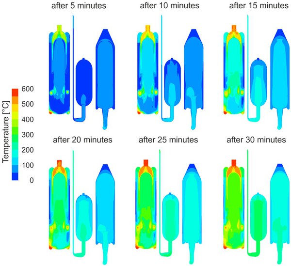
The software packages MATLAB® Simulink® and ANSYS® Fluent® are used for the dynamic modeling of fuel gas production and fuel cell systems. Simulink® enables hierarchical modeling using graphical blocks. Simulink® provides a basic set of continuous and discrete logic blocks. In addition, the IET-4 integrates its own codes into the model using so-called S-functions. The data flow between the blocks is realized graphically using connecting lines. The characteristic data of the individual components are stored in Simulink on its surface or in C-code (S-functions) programmed models, data tables or in MATLAB® (m-files). For dynamic modeling, the experimental determination and/or theoretical derivation of the dynamic behavior of the components is crucial. In recent years, the starting behavior of fuel cells for on-board power supply has been investigated. With the help of modeling with Simulink, suitable processes and starting components can be selected in advance. The exact influence of the reactor geometry on the start-up time can be verified with dynamic modeling using ANSYS® Fluent®. This identifies the locations in the reactors and systems that negatively influence the system's start-up behavior. To optimize the start-up process using spatially resolved two-dimensional fluid dynamic simulations, experimentally validated two-zone models for porous bodies are used in transient simulations. The coupling of the reactors into one system is realized with the help of user-defined functions. An optimized meshing method was developed for the three-dimensional optimization of the systems in order to significantly reduce the calculation time of the simulations without sacrificing the quality of the results. In this process, the calculation grids are created with predominantly conformal interface meshing but with occasional use of interfaces.
