Equipment for component and layer production
Tape casting
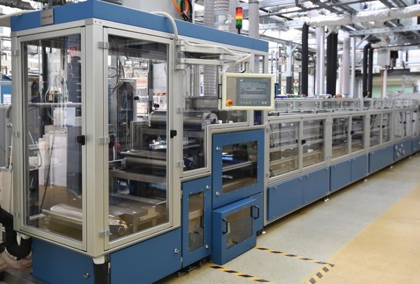
JuCast 3-500 sequential tape casting bench
Description
The JuCast 3-500 sequential tape casting bench (manufacturer: KMS Technology Center, Dresden, Germany) is suitable for the production of two-dimensional green films in various thicknesses with up to 3 layers, which can be produced in a single casting. Typical layer thicknesses range from 10 to 1000 µm. Production involves casting a slurry consisting of solvents, powder(s) and organic additives such as binders, plasticizers and dispersants. The slurry is cast onto a PET film to a defined height, which is determined by a squeegee, and then dried. The dried green film is then separated from the PET film. The green film obtained in this way is then sintered. During this process, the organic compounds are burned out.
Specifications:
• 3 casting heads for casting thicknesses from 10 to 1000 µm
- 1. The slip can be applied using a roller doctor blade or granite casting shoe with doctor blade.
- 2. The slip can only be applied using a roller doctor blade.
- 3. The slip can be applied using a roller doctor blade or granite casting shoe with doctor blade.
• Maximum casting width 500 mm
• Various thickness sequences possible (e.g., thin-thin-thick)
• Five separate heating/cooling chambers
• For ceramic, metal, and mixed powders
• Solvent-based slurries
• Layer thickness monitoring using laser optics
• Integrated assembly unit
• Separate punching unit
KAROcast 300-7 film casting system
Description:
The KAROcast 300-7 micro tape casting bench (manufacturer: KMS Technology Center, Dresden, Germany) follows the same casting principle as the JuCast. However, this system is specifically designed for very thin layers. Dry layer thicknesses can vary between approx. 3 and 100 µm. The ceramic layer is dried immediately after casting within the system; increased casting and drying temperatures can be set.
Specifications:
• Casting width up to 300 mm, length approx. 1 m in batch operation
• Thickness approx. 3-100 µm
• Heatable drying area
• Suitable for organic solvents

MULTIcast laboratory casting bench for casting and drying thin layers on polymeric tapes
Description:
The MULTIcast tape-casting bench (manufacturer: KMS Technology Center, Dresden, Germany) is designed for layers of varying thicknesses, depending on the casting mold used. The system has two working areas that can be used for casting with different settings. Work area 1 consists of a single two-meter-long granite casting base, while work area 2 consists of an approximately one-meter-long granite casting base with vacuum holes and an aluminum plate, also approximately one meter long, which can be temperature-controlled (heated/cooled). Each work area has its own unwinding and winding device for transporting the polymeric tape. A linear axis with retractable carriers for casting boxes is located centrally above the two work areas and serves both work areas. When casting the tapes, two functions are available at both work areas: casting with moving polymer tape and stationary casting box, or casting with moving casting box and stationary tape. This capability makes it possible to target specific areas and produce multiple coatings. Controlled drying takes place immediately after casting within the system. The system is used for the development of new ceramic or metallic slips and for the initial adjustment of casting parameters. Once the slip and casting have been optimized, larger quantities of slip can then be cast on the JuCast.
Specifications:
• Casting length working area 1 approx. 2 m, casting width up to approx. 200 mm
• Casting length working area 2 temperature-controlled plate approx. 1 m, vacuum plate approx. 1 m, casting width up to approx. 200 mm
• Casting mold interchangeable
• Casting thickness varies depending on casting box (~ 50 µm to 2500 µm)
• Diameter of vacuum holes 0.6 mm
• Temperature control from -20°C to +80°C
• Solvent-based slip
• Controlled drying within the system

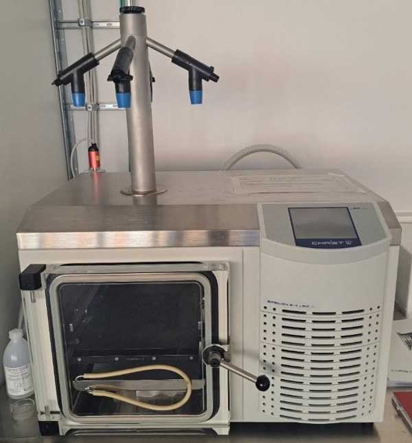
Freeze casting
Freeze casting enables the production of anisotropic pore structures in ceramic materials. The shape of the pores can be varied by using different solvents.
Screen printing
In screen printing, a paste is pressed through a screen mesh onto a flat substrate using a squeegee to achieve a reproducible, even application across the entire printing area. The thickness of the resulting layer can be varied by selecting the screen mesh. Layers with a thickness of just a few micrometers are already possible. In stencil printing, the screen mesh is replaced by a metal stencil in order to print thicker 3D structures.
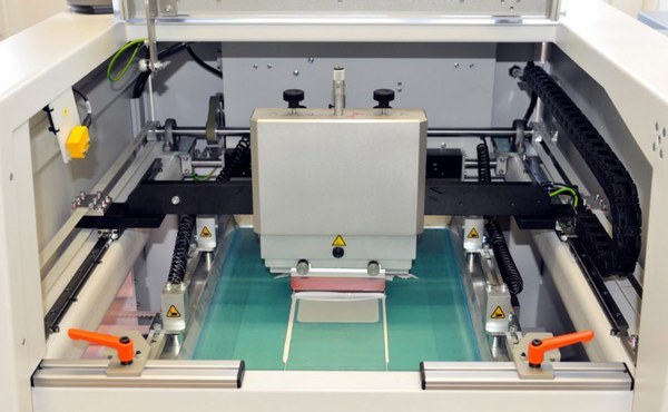
Semi-automatic screen and stencil printer EKRA E2
The semi-automatic screen and stencil printer Ekra E2 allows control of process parameters such as lift-off, squeegee pressure, and speed via software, ensuring maximum reproducibility of the printing process. The integrated camera system allows for highly accurate alignment of the print material. Various squeegee, screen, and stencil types are available for printing, allowing almost any desired layer thickness and geometry to be printed.
Specifications:
• Layer thicknesses from 1 µm to 1 mm
• Print field sizes up to 100 x 30 cm
• Camera system for sample positioning
• Squeegee pressures adjustable up to 5 bar
• Individual adjustment of squeegee speeds (forward and backward) up to max. 500 mm/s
• Various printing variants selectable (automatic sequence)
• Saving of parameter sets
Powder Injection Moulding (PIM)
The institute has two injection molding systems for the production of complex-shaped functional components from ceramic and metallic powders. The Boy XS system (Dr. Boy GmbH & Co. KG) is particularly suitable for feedstock development and for demonstrating the basic feasibility of injection molding processes on a laboratory scale. The system is hydraulically operated with a maximum clamping force of 100 kN. The plasticizing unit with a diameter of 16 mm enables the processing of small feedstock volumes from approx. 50 cm3. The dosing volume can be varied in the range of 0.1 – 8 cm3. The system can also be used to effectively injection mold small quantities of powder. For scaling the technology to larger feedstock volumes, the institute operates the 370U 2K allrounder 700-100-100 two-component injection molding machine. The machine is designed for industrial series production. With a suitable injection mold design, the machine enables the production of a component from two different feedstocks. The combination of a horizontal and vertical injection molding unit enables the production of components from two different materials (e.g., metal/ceramic or dense/porous combinations). The clamping force of the system is 700 kN, and the maximum dosing volume is approximately 50 cm3.
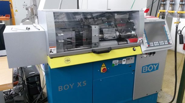

View of the open injection mold and heated injection device.

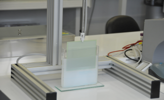
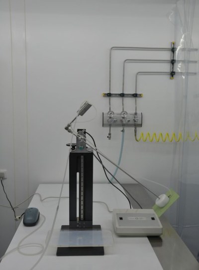
Dip Coating
The technical term “dip coating” refers to a group of coating processes in which a substrate is dipped into a coating solution and then removed again. When the substrate is removed, a thin film of the coating material remains on the substrate. After the substrate has been coated, it is usually dried and fired to form a ceramic.
Dip coating is often used to apply thin-film coatings with special properties (e.g., nanostructured, microporous, catalytically active) to flat or cylindrical substrates without the need for complicated or expensive equipment.
The coating solution can be applied to the substrate using various methods.
In classic dip coating, a substrate to be coated is completely immersed in a coating solution and then slowly withdrawn. As it is withdrawn, a thin film is deposited on the surface. This method is also frequently used for large-scale applications, e.g., in the automotive and glass industries.
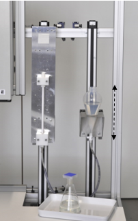
A variation of this process involves dipping only one side of the substrate, which is moved tangentially in a clockwise direction through the coating liquid.
When coating the inside of tubular substrates, the substrate is not coated by complete immersion in the solution, but by a special process in which the liquid is moved into the interior of the tube under pressure. This can be done, for example, with the aid of a pump or using the principle of communicating vessels.
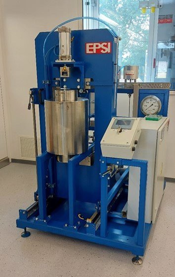
Cold isostatic pressing (CIP)
Cold isostatic pressing (CIP) is based on the effect that pressure applied to a liquid spreads evenly in all directions (known as Pascal's principle). Inside the liquid, this leads to a homogeneous pressure distribution, which can be used for shaping ceramic and metallic powders if the powder is encapsulated in an elastic matrix. Elastic plastics (elastomers) are the preferred matrix materials for the molds. The main components of a cold isostatic press are the container filled with the pressure transmission medium, the high-pressure generator, the sealing system, the overpressure protection, and the system control. An oil-water emulsion is used as the pressure transmission medium.
Betriebsparameter CIP 400-125*300Y:
Recipient inner diameter: 125 mm
Recipient inner height: 300 mm
Max. sample dimensions: limited by volume
Max. filling height: 295 mm
Recipient volume: 3.7 liters
Maximum nominal operating pressure: 4000 bar (400 MPa)
Maximum permissible operating pressure: 4400 bar (440 MPa)
Safety factor: 1.1 (4840 bar, 484 MPa)
Physical vapor deposition (PVD)
Physical vapor deposition processes are used at IMD-2 for electrochemical storage devices and converters, i.e., batteries, fuel cells, or electrolysis cells.

Principle
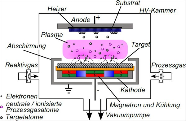
In physical vapor deposition, a material is transferred to the gas phase at the atomic level. This gas encounters the sample and is deposited as a thin film, on a nanometer or micrometer scale depending on the deposition time. During the entire deposition process – transition to the gas phase - transfer of the material to the sample - condensation on the sample surface – only the aggregate state of the material is changed: from “solid” or “liquid” to “gaseous” and back to “solid.” Normally, the material is not changed during the deposition process.
PVD facilities
The IMD-2 currently has four different PVD facilities, each with different areas of application.
PVD system CS 400 ES
The PVD system CS 400 ES (Von Ardenne GmbH) is used for air-insensitive coatings in the field of electrochemical storage and fuel cells and enables cathode sputtering in direct current (DC) and high-frequency (RF) operation, as well as electron beam evaporation. Both processes can also be carried out reactively, i.e., in the presence of a gas with which the material can react in the gas phase. To adjust the morphology, the coatings can be deposited at temperatures up to 800 °C and, optionally, with additional ion support. Planar substrates up to a diameter of 6 inches (approx. 15 cm) can be coated.

PVD system CS 800 ES
The PVD system CS 800 ES (Von Ardenne GmbH) features enhancements specifically tailored to battery manufacturing. The modular design, consisting of two sputtering chambers and one electron beam evaporation chamber, enables the deposition of complete batteries within the system without removing the samples from the equipment. This reduces contamination to a minimum and significantly increases the quality of the cells obtained. In addition, the system is connected to a glovebox system so that even air-sensitive layers can be produced and initial analyses can be carried out immediately after synthesis without interrupting the inert atmosphere. Planar substrates up to a diameter of 6 inches (approx. 15 cm) can be coated at temperatures up to 1,000 °C and optionally in DC or RF mode, reactively and with additional ion support.

PVD system CS 400 S
The CS 400 S PVD system (Von Ardenne GmbH), also equipped with a glove box for air- and moisture-sensitive samples, offers the option of sputtering in a confocal geometry of up to four sputter targets on planar substrates with a diameter of up to 6 inches (approx. 15 cm). It can be coated using DC, RF, and medium-frequency pulse sputtering, temperatures up to 800 °C, and optionally reactively and with additional ion assistance. A bipolar source system is also implemented.

PVD system CC800/9
The CC800/9 PVD system (CemeCon AG) coats using high-power pulsed magnetron sputtering (HPPMS). Among other things, this enables improved adhesion of the layers and homogeneous, dense layers even on complex geometries. DC sputtering of up to four sputter targets and HPPMS sputtering of up to two sputter targets, each with maximum sample substrate temperatures of approx. 800°C, are possible.

Thermal spraying
Thermal spraying encompasses a whole family of processes that differ in terms of their capabilities for processing a wide variety of materials. In thermal spraying, particulate starting materials in the form of powders or suspensions are injected into a hot gas torch, melted, and accelerated onto the substrate. A wide range of process parameters, such as gas composition, gas flow, current, spraying distance, particle size distribution, carrier gas flow, ambient pressure, etc., influence the degree of melting and the velocity of the particles and thus have a significant impact on the resulting microstructure, adhesion, and stress state.
The hot gas and particle properties in flight can be analyzed to gain a better understanding of the processes and to ensure quality.
Plasma spraying
In plasma spraying, particulate starting materials are melted in a plasma jet and accelerated towards the substrate, which is generated by ionizing a gas stream.
Atmospheric plasma spraying (APS) is particularly suitable for the deposition of high-melting ceramics, such as oxide ceramics for thermal insulation layers.
Burners: SinplexPro, TriplexPro-210, Axial III, F4-MB, 9MB, F100 Connex (internal coatings)

Suspension plasma spraying (SPS) is an APS process in which a liquid suspension is used as a precursor. This enables the processing of particles in the sub-micrometer range and thus novel, microstructured coatings.
Torch: TriplexPro-210, Axial III
With low pressure plasma spray (LPPS) or vacuum plasma spraying (VPS), ceramic and, in particular, metallic coatings can be produced without oxygen absorption.
Burners: F4-VB, Sinplex 03C, 03CP

Low-pressure thin-film plasma spraying (LPPS-TF) is a further development of vacuum plasma spraying at low pressure. This enables the deposition of thin, gas-tight layers.
Torches: F4-VB, 03CP

Plasma spray physical vapor deposition (PS-PVD) also takes place at low pressure, but the performance is even higher. With suitable powders, it is even possible to deposit novel, columnar structures from the vapor phase.
Torch: O3CP

Cold gas spraying
In cold gas spraying, a moderately preheated, compressed gas (N2, in exceptional cases also He) expands through a Laval nozzle and reaches very high speeds in the supersonic range. When the powder particles hit the substrate at a critical velocity that depends on the material, they become plasticized and form tightly adhering, dense layers. The process is particularly suitable for oxidation-sensitive materials.
Systems: Kinetiks 8000, Impact 5/11

High-velocity oxyfuel
High-velocity oxyfuel (HVOF) is a hydrogen- or methane-oxygen process with air or N2 shielding gas, which is based on combustion. In contrast to plasma spraying, HVOF enables gas velocities in the supersonic range and thus significantly higher particle velocities at comparatively moderate temperatures of the fuel gas flame. This makes the process particularly suitable for wear-resistant alloys and MCrAlY bonding layers.
Burners: DiamondJet 2600, DiamondJet 2700

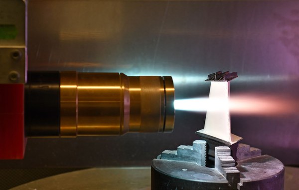
In contrast to HVOF, the High Velocity Air Fuel (HVAF) process uses propane as the fuel gas, which is burned with large amounts of compressed air. Compared to HVOF, even higher gas and particle velocities are achieved at lower temperatures.
Burner: Uniquecoat M3

Hot gas jet from a Uniquecoat M3 burner with injected powder; “shock diamonds” indicate supersonic flow.
Laser processing
Trumpf Laser Cell 3008
• Laser cladding TruFiber
• Laser ablation TruMark

Glovebox system
A large argon glovebox (GS Glovebox Systemtechnik GmbH) with seven workstations is available for work on battery materials that must be carried out in a protective atmosphere. These are directly connected to an argon high-temperature furnace (LK1200-200-400-1, HTM Reetz GmbH) and a physical vapor deposition (PVD) system (Univex 350G, Leybold GmbH). This enables the deposition of lithium or sodium and immediate further processing into full cells.


For working with solvent-containing substances in a protective atmosphere, a glovebox with four workstations is directly connected to the above glovebox. The equipment allows a complete tape casting process under a protective atmosphere. From mixing the slurry in the mixer (ARE-250, Thinky Inc.) to film casting on a film casting bench (MSK-AFA-IIID Automatic Thick Film Coater, MTI Corporation) to the hot press (YLP-HP80, MIT Corporation, Tmax = 150 °C, pmax = 9 kN), all the necessary equipment is available.
