Laser-Produced Light Sources
X-ray Sources
There is a growing demand for bright, ultrashort X-ray sources with femtosecond (fs) duration. Those provide insight into ultrafast, time-resolved structural dynamics of materials, such as chemical reactions, phase transitions, fs triggered crystal lattice dynamics, etc. Betatron radiation and Thomson/Compton scattering based on relativistic electron beams generated from laser plasma acceleration promise to provide such tabletop X-ray sources. Betatron radiation produces X-rays through transverse oscillation of the electrons in a laser wakefield acceleration process. Experiments demonstrated the production of ~100 keV, fs X-rays with peak brightness up to 1022 photons/(s mm2 mrad2 0.1% bandwidth). For Thomson/Compton scattering, high density electron beams from laser wakefield accelerators reflect a counter-propagating optical-frequency laser pulse. The frequency of the latter can be upshifted by 4γ2 due to the double relativistic Doppler effect, where γ is the Lorentz factor of the beam. A recent experiment demonstrated hundreds of keV, fs X-rays with peak brightness of 1021 photons/(s mm2 mrad2 0.1% bandwidth).
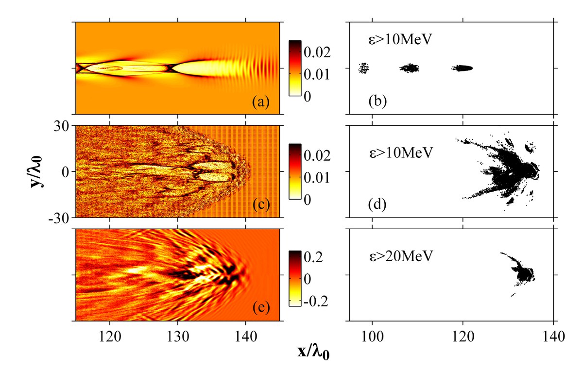
To explain the experimental observation, Particle-in-Cell (PIC) simulations are crucial. PIC simulations can reproduce the whole process from high energy electron generation by laser plasma interaction to the X-ray emission via the movement of the generated electrons in plasma fields and laser fields. On the other hand, simulations can test novel schemes to optimize the X-ray generation before experiments are performed. The figure is a typical result of a PIC simulation, showing the distribution of high energy electrons produced from a cluster plasma irradiated by a relativistic intense laser pulse.
Circularly Polarized Harmonic Generation
Circularly polarized (CP) harmonics, coherent sources of radiation in the XUV and soft X-ray range, are of great importance due to their application in studying the magnetic properties of matter. CP laser pulses could potentially generate CP harmonics. However, within the electromagnetic field of a single CP pulse, harmonics are suppressed in both gas and plasma targets. Generally, recombination of ionized electrons with the parent ions is the process for the generation of the harmonics in gas targets, but this does not take place when the driver field is circularly polarized. In a plasma medium the same ‘exclusion’ principle applies, but the reason is the suppression of the high-frequency density fluctuations and relativistic nonlinearities.
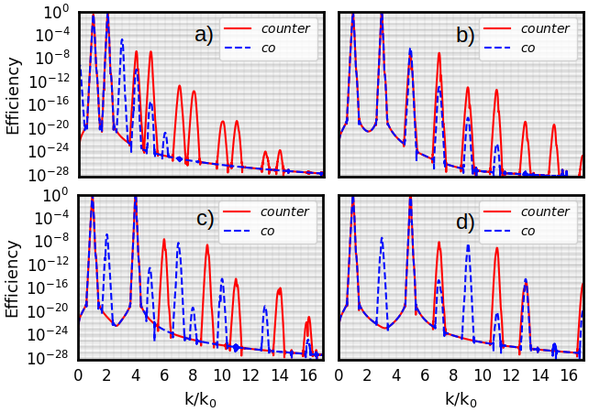
Recent studies have demonstrated generation of CP harmonics in the field of two counter-polarized CP pulses of different wavelengths (400nm + 800nm) in a gas target (O. Kfir et al., Generation of bright phase-matched circularly-polarized extreme ultraviolet high harmonics, Nature Photonics 9, 99 (2015)). According to this experiment, CP harmonics are generated in a way that every third harmonic is suppressed. Follow-up numerical and analytical studies aiming for higher intensity harmonics imply that a similar effect occurs in the plasma targets (Z. M. Chitgar et al., Theory of circularly polarized harmonic generation using bi-colour lasers in underdense plasmas, Plasma Physics and Controlled Fusion 63(3) , 035023 (2021)). Superposition of two CP drivers results in acceleration and deceleration of the particles in each cycle, resulting in coherent radiation of X-rays.
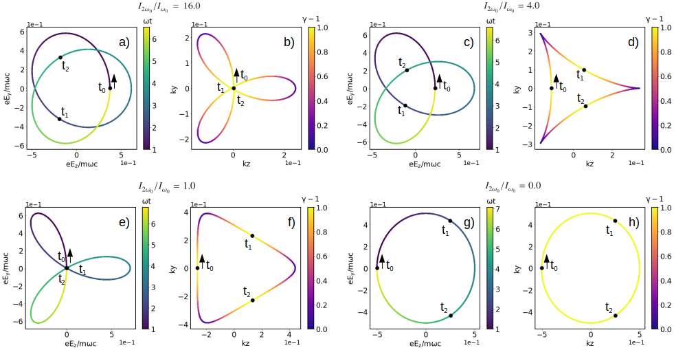
According to this study, for drivers with a frequency ratio of q, if the pulses are counter-polarized the following harmonics appear; (q + 1) m ± 1 and (q + 1) m ± q. This means that for q=2, every third harmonic is suppressed as in the gas target. Accordingly for co-polarized pulses a set of selection rules can be deduced, where only these harmonics appear: (q − 1) m ± 1 and (q − 1) m ± q. Additionally, the hellicity of the harmonics can be predicted by this model.
References
- O. Kfir et al., Generation of bright phase-matched circularly-polarized extreme ultraviolet high harmonics, Nature Photonics 9, 99 (2015)
- Z. M. Chitgar et al., Theory of circularly polarized harmonic generation using bi-colour lasers in underdense plasmas, Plasma Physics and Controlled Fusion 63(3), 035023 (2021)
Toward near-field calculation of Betatron Radiation
Simulation study of laser-driven radiation sources, ranging from UV (∼100 nm) to hard X-ray (10−3nm) is a way to gain insight into their characteristics. However, conventional Particle-in-Cell (PIC) simulations are not often useful in this case. Capturing ultra-short wavelengths, such as betatron radiation from oscillating electrons within a plasma wakefield driven by a laser, demands PIC simulations with very high resolution beyond the capability of supercomputers.
PIC codes in this context are often used to first compute the charged particle motion. This data can then be used to calculate the far-field emission based on the charged particle trajectories using the Liénard-Wiechert potentials (see references below).
CASPER (Coherence and Spectral Post-processor for Emitted Radiation) is an example of such a far-field radiation calculator (U. Sinha and N. Kumar, Pair-beam propagation in a magnetized plasma for modeling the polarized radiation emission from gamma-ray bursts in laboratory astrophysics experiments, Physical Review E 101, 063204 (2020)). CASPER is a parallel code that computes the Fourier spectrum of the electric field radiated from a collection of accelerated charged particles and the corresponding Stokes parameters by post-processing their trajectories extracted from a particle-in-cell (PIC) simulation.
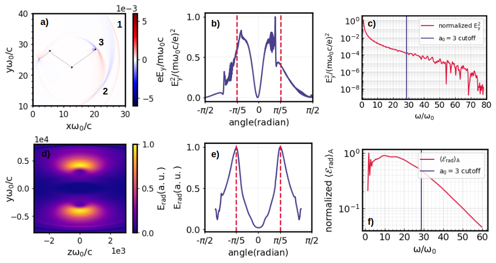
An alternative method to calculate the radiation is to extract the particle trajectories from a PIC code and use it as a source term in a high-resolution field solver to calculate the near-field radiation. Preliminary studies have been done to simulate the Thomson scattering arising from the motion of electrons in a laser field (Z. Chitgar, Optical control of laser-driven X-ray and XUV radiation sources, Dissertation, RWTH Aachen University (2021)). Results from the near-field calculator are in a good agreement with the far-field (CAPSER) in terms of radiation angular distribution energy range.
Applying this method to calculate the extremely high-frequency betatron radiation is a bigger challenge, where the field solver needs further optimization.
References
J. D. Jackson, Classical electrodynamics, 1999
U. Sinha and N. Kumar, Pair-beam propagation in a magnetized plasma for modeling the polarized radiation emission from gamma-ray bursts in laboratory astrophysics experiments, Physical Review E 101, 063204 (2020)
V. Horný et al., Optical injection dynamics in two laser wakefield acceleration configurations, Plasma Physics and Controlled Fusion 60, 064009 (2018)
Z. Chitgar, Optical control of laser-driven X-ray and XUV radiation sources, Dissertation, RWTH Aachen University (2021)